Switches are essential to Molded-Case Circuit Breakers setting and operation
By Mike Bolduc | September 18, 2018
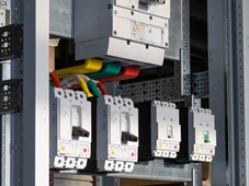
Molded-case circuit breakers (MCCBs) provide protection where miniature circuit breakers (MCBs) are too small or inflexible. They typically offer higher current capability, up to thousands of Amperes, as well as the ability to set the trip current on the front panel.
In common with MCBs, MCCBs offer two primary types of fault protection:
- Overload protection is achieved through the use of a bi-metallic strip. Under normal operating conditions, current passes through this strip continuously. However, in the event that there is an elevated current for longer than is desired, the heating effect bends the strip, breaking the contact and removing the power from the load.
- Fault protection is an electromagnetic function with an instantaneous response, as fault currents need to be interrupted immediately. Whenever a fault occurs, a solenoid coil inside the MCCB is energized and a contact is tripped, removing the power to the circuit. Many MCCBs include arc dissipation measures, as large currents are being switched.
In common with almost any electronic/electromechanical device, MCCBs are becoming “connected” and form an essential part of smart factories, where they can be used to monitor and manage the energy usage and cost of running of large machinery.
Also, in common with most electronic/electromechanical equipment, MCCBs rely on switches to provide vital functions including setting the main parameters (trip current and time delays), and as auxiliary switches to execute functions once the MCCB has been tripped.
- For setting the trip current/time delay a rotary PCB-mount DIP switch is most commonly used. Ensuring that the current is set correctly is of primary importance for safety, avoidance of nuisance trips, and to ensure that any downstream equipment is not damaged should a fault occur. To achieve this, rotary switch contacts have a positive detent so that only integer points can be set.
Setting rotary DIP switches requires a tool or a special actuator for manual use. Many manufacturers offer a wide variety of actuator types as semi-custom options, allowing manufacturers of MCCBs to choose the method of actuation.
- The auxiliary switch is most often a micro switch to provide system notification and/or to control external devices when the MCCB is tripped. Control of warning lights, relays and external power supplies can require around 10A to 15A range, while PLC control currents are much lower. The need for this configuration flexibility generally necessitates a custom design instead of a catalog switch.
Mechanical compatibility with the MCCB, enabling quick and easy removal of the switch for re-configuration, usually involves adding an overmolded housing with quick-release latches as well as customized wiring to suit the specific application and make installation easier.
Two switch types commonly found in MCCBs are as follows.
RTE series – low-profile rotary DIP switch
This RTE series rotary DIP switch is primarily used for setting the trip current and/or time delay.
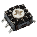
Figure 1: The RTE series offers designers various options for PCB mounting
The RTE offers 4, 10 or 16 positions, in BCD, Gray or hexadecimal code versions, or a simple single-pole output. Mechanical options include vertical, horizontal (pin-thru and SMD) and reverse versions.
The standard LCP actuator accepts a straight or crosshead screwdriver, or an optional shaft can be specified for manual operation. The top plate can be specified as silver or black, and an ESD protection plate is also available as an option.
The movable contacts are made from gold-plated copper alloy for reliability, and their shape provides a positive detent to each position, ensuring accurate operation. The RTE switches cover the industrial temperature range of -25°C to +85°C.
TM series – miniature snap-acting switches
The UL-rated TM series forms the basis of many custom snap-in solutions for MCCB auxiliary switches.
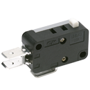
Figure 2: Versatile and easily customized – the TM series
The momentary-action switches are 15A rated and offer multiple single-pole configurations. Lower-current versions are available in mechanically identical packages for PLC control applications. Other options include the operating force and pivot position of the actuator as well as actuator type.
The switches operate at temperatures between -55°C and +150°C, making them ideal for use in harsh industrial applications. A range of terminations are available, including two sizes of quick-connect solder terminals and screw terminals – and leads can be terminated as required for any factory-produced custom assembly.
In their bare form, either imperial or metric screws typically mount the switches, although customization by C&K to create a snap-in fitting with correctly sized leads is a very popular option that can be arranged by contacting the factory.

Mike Bolduc
Global Segment Manager
Industrial